Power supply circuit plays an essential role in every electrical and electronic circuit to provide the electrical power to the owl circuit or loads like machines, computers, etc. These different loads require different forms of power at various ranges and characteristics. So, the power is converted into the desired form by using different power converters. Basically, different loads work with various types of power supplies like SMPS (switch mode power supply), AC power supply, AC to DC power supply, programmable power supply, high voltage power supply & uninteruptable power supply.
What is SMPS (Switch-Mode Power Supply)?
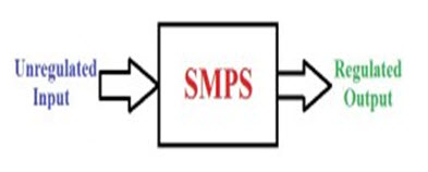
SMPS is defined as, when the power supply is included with the switching regulator from converting electrical power from one form to another form with necessary characteristics is called switch mode power supply. This power supply is used to attain regulated DC o/p voltage from the DC i/p voltage or unregulated AC.
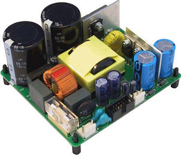
SMPS
SMPS is a complicated circuit like other power supplies, it supplies from a source to the loads. MPS is crucial for different electrical and electronic appliances which consumes power and also for designing electronic projects.
Topologies of SMPS
Topologies of SMPS are categorized into different types such as AC-DC converter, DC-DC converter, Forward Converter and Flyback converter.
Working principle of Switch Mode Power Supply
The working of a switch mode power supply topologies is discussed below.
DC-DC Converter SMPS Working
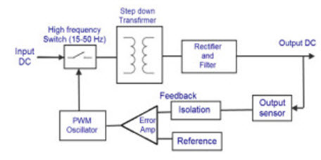
In this power source, a high voltage DC power is directly acquired from a DC power source. Then, this high voltage DC power is switched usually in the range of 15KHz-5KHz. And, then it is fed to a step down transformer unit of 50Hz. The o/p of this transformer is fed to the rectifier, them this rectified o/p power is used as a source for loads, and the oscillator ON time is controlled and a closed loop regulator is formed.
DC to DC converter SMPS
The switching-power supply o/p is regulated by using Pulse Width Modulation shown in the above circuit, the switch is driven by the PWM oscillator, then indirectly the step down transformer is controlled when the power fed to the transformer. Therefore, the o/p is controlled by the pulse width modulation, as this o/p voltage and PWM signal are inversely proportional to each other. If the duty cycle is 50%, then the max power is transferred through the transformer, and if the duty cycle drops, then the power in the transformer also drops by decreasing the power dissipation.
AC -DC Converter SMPS Working
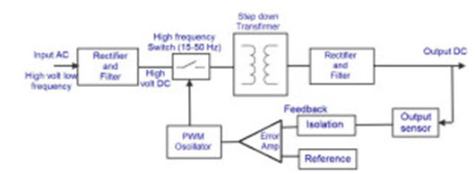
This type of SMPS has an AC i/p and it is converted into DC by using rectifier & filter. This unregulated DC voltage is fed to the power factor correction circuits as it is affected. This is because around the voltage peaks, the rectifier draws short current pulses having significantly high-frequency energy that affects the power factor to reduce.
AC to DC converter SMPS
It is almost related to the above discussed converter, but in the place of DC power supply, here we have used AC i/p. So, the mixture of the rectifier &filter, this block diagram is used for converting the AC to DC and the switching operation is done by using a power MOSFET amplifier. The MOSFET transistor consumes low on-resistance & can resist high currents. The frequency of the switching is selected such that it must be kept low to normal human beings (above 20KHz) and action of switching is controlled by a feedback using the PWM oscillator.
Again, this AC voltage is fed to the o/p of the transformer shown in the above figure to step up or step down the levels of voltage. Then, the this transformer’s o/p is rectified & smoothed by using the o/p filter and a rectifier. The o/p voltage is controlled by a feedback circuit by likening it with the reference voltage.
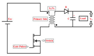
Fly-back Converter SMPS Working
The SMPS circuit which has very low o/p power (less than 100W) is called as fly-back converter SMPS. This type of SMPS is very low and simple circuit compared with other SMPS circuits. This type of SMPS is used for low power applications.
Fly-back Converter type SMPS
The unregulated i/p voltage with a constant magnitude is changed into a preferred o/p voltage by switching fast using a MOSFET; the frequency of switching is around 100 kHz. The voltage isolation can be attained by using a transformer. The operation of the switch can be controlled by using a PWM while executing a practical fly-back converter.
Fly-back transformer shows dissimilar characteristics compared to normal transformer.Fly-back transformer includes two windings which acts as a magnetic coupled inductor. The o/p of this transformer is delivered through a capacitor and diode for filtering as well as rectification. As shown in the above figure, the o/p of the SMPS can be taken as voltage across the filter capacitor.
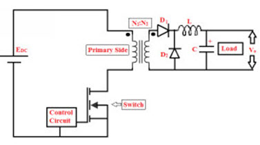
Forward Converter type SMPS Working
This type of SMPS is almost same to the fly back converter type SMPS. But, in this type of SMPS a control is connected at the o/p of the secondary winding of the transformer to control the switch. As compared to the fly back converter, the filtering and rectification circuit is complicated.
Forward Converter type SMPS
This is also called as a DC-DC buck converter, along with a transformer which is used for scaling and isolation. In addition to the “D1” diode & “C” capacitor, an inductor L & a diode D are connected at the end of the o/p. If ‘S’ switch gets switched ON, then the i/p is given to the transformer’s primary winding. Therefore, a scaled voltage is produced at the transformer’s secondary winding.
Therefore, the D1 diode gets forward biased & scaled voltage is passed through the LPF proceeding the load. When the switch S is turned ON, then the currents through the winding reaches to zero, However the current through the inductive filter & load cannot be changed shortly, and a lane is offered to this current by the coasting diode D2. By using the filter inductor, the required voltage across the D2 diode & to keep the electromagnetic force necessary for maintaining the stability of the current at inductive filter. Even though the current is falling against the o/p voltage, almost the constant o/p voltage is sustained with the existence of the large capacitive filter. It is regularly used for various switching applications with a 100 W to 200 W power range.
This is all about switch mode power supply and its types which involves Buck converter, Buck-boost converter Self Oscillating fly-back converter, Boost converter, Cuk, Sepic, Boost-buck. But, a few types of SMPS’s are discussed in this article they are AC-DC converter, DC-DC converter, Forward and Fly-back converter. Furthermore, any information regarding the types of SMPS, fell free to give your feedback to give your suggestions, comments in the comment section below.
What is Switching Mode Power Supply (SMPS) And its Application?
Switch Mode Power Supply
The power supply circuit in any electrical and electronic circuit plays a vital role to give the power to the entire circuit. The different circuits require various kinds of power at different ranges and characteristics. So, the power is changed into the required form by adopting different power converters. Fundamentally, different types of circuits work with various kinds of power supplies such as SMPS. The term SMPS stands for switch mode power supply, AC to DC power supply, AC power supply, high voltage power supply programmable power supply, and UPS (uninterruptible power supply).
What is a Switch Mode Power Supply?
The term SMPS is defined as when the power supply is involved with the switching regulator to change the electrical power from one form to another form with required characteristics is called SMPS. This power supply is used to achieve regulated DC output voltage from the DC input voltage (or) unregulated AC. SMPS is a complex circuit such as other power supplies, it provides the supply from a source to the loads. SMPS is very important for different appliances which consume power and also for making electronic projects.
SMPS
Working Principle of an SMPS
A switching regulator does the regulation in the switch mode power supply. A series switching element switches the current supply to a smoothing capacitor turn ON and OFF. The voltage on the smoothing capacitor controls the time when the series element is switched. The constant switching of the capacitor keeps the voltage at the necessary level.
SMPS Circuit
AC power first flows through the fuses & a line filter, then it is resolved by a full wave bridge rectifier. The voltage which is resolved is next used to the PFC (power factor correction) pre-regulator followed by the downstream DC to DC converter. Most of the computers and small machines utilize IEC (International Electrotechnical Commission) style i/p connector. As for o/p connectors and pinouts, excluding for some industries like PC & compact PCI. In general, they are not consistent and are left up to the manufacturer.
Like every electronic device, the switch mode power supply also comprises some active & passive components. And like each of those devices, it has its own benefits and drawbacks.
Different Types of SMPS
The different types of SMPS include the following
D.C. to D.C. Converter
Forward Converter:
Flyback Converter
Self-Oscillating Flyback Converter
DC-DC Converter
The main power received from the AC main is resolved and filtered as high voltage DC. Then, it is changing at an enormous rate of speed and fed to the main side of the step-down transformer. This transformer is only a segment of the size of an equivalent 50 Hz unit, thus releasing the size and weight problems. The filtered and rectified o/p at the minor side of the transformer. Then it is now sent to the o/p of the power supply. A sample of this o/p is sent back to the button to control the o/p voltage.
D.C to D.C Converter
Forward Converter
In a forward converter, the choke transmits the current when the transistor is leading as well as when it is not. The diode transmits the current through the OFF period of the transistor. Thus, the flow of current into the load during both the periods. The choke stores energy during the ON period and also permits some energy into the o/p load.
Forward Converter
Flyback Converter
In this converter, the magnetic field of the inductor supplies the energy throughout the ON period of the switch. The energy is collapsed into the o/p voltage circuit when the button is in the open state. The duty cycle controls the output voltage.
Flyback Converter
Self-Oscillating Flyback Converter
This is the most simple converter based on the principle of the flyback. Throughout the conduction time of the switching transistor, the flow of current through the transformer primary switches ramping up linearly with the angle equal to Vin/Lp. The induced voltage in the secondary winding and the feedback winding make the fastest recovery rectifier reverse biased and hold the conducting transistor ON. When the primary current touches a peak value ‘Ip’, where the core activates to saturate, the current inclines to increase very sharply. This cannot be supported by the fixed base drive offered by the feedback winding. As a result, the switching activates to come out of saturation.
Features between SMPS and Linear power Supply
Features
Linear Power Supply
SMPS
Efficiency
25-50 %
65-75 %
Temperature rise
50-100oC
20-40oC
Ripple value
Even 5 mV possible
Higher 25-50 mV
Overall regulation
0.1 %
0.3 %
RF interference
None
Can cause problem if not properly shielded
Magnetic material
Stalloy or CRGO core
Ferrite core
Weight
20-30 W\kg
About 60 W\kg
Reliability
More reliable
Depends on the switches
Transient response
Faster
Slower (in ms)
Complexity
Less
More
Advantages and Disadvantages
The main advantage of the SMPS is greater efficiency than linear regulators because the switching transistor dissolves little power when working as a switch.
The size of SMPS is a smaller size and lighter in weight from the removal of heavy line frequency transformers, and similar heat generation. The standby power loss is frequently much less than transformers.
Disadvantages of SMPS include better complexity, the generation of high-amplitude, the high-frequency energy that the LPF must block to avoid EMI (electromagnetic interference), harmonic frequencies, and a ripple voltage at the switching frequency.
The low-cost SMPSs may pair electrical switching noise back onto the main power line, causing interference with equipment connected to the similar phase. Non-power factor corrected power supplies also source harmonic distortion.
Furthermore, the SMPS is intended to make more efficient doing the most effective conversion process. The main focus of engineers in building the SMPS efficient includes Higher o/p power, low voltage, power density and Using a switching device such as Schottky diode.We hope that you have got a better understanding of this concept or to implement any electrical projects,
I am the owner of the 911electronic.com website. We have an article on the subject of a simple-dial diode on your website. We describe in it the principle of operation, structure, and characteristics for the use of a rectifying diode. The article describes various types of rectifier bridges.
The SMPS systems that you describe consist of rectifier bridges, the description of which is not sufficient.
Please check our article at: https://911electronic.com/rectifier-diode/ If you find that our article may in some way broaden the knowledge provided by the reader in your article, please add a link in the text to our article. Users will certainly benefit from this.


I am the owner of the 911electronic.com website.
ReplyDeleteWe have an article on the subject of a simple-dial diode on your website. We describe in it the principle of operation, structure, and characteristics for the use of a rectifying diode. The article describes various types of rectifier bridges.
The SMPS systems that you describe consist of rectifier bridges, the description of which is not sufficient.
Please check our article at: https://911electronic.com/rectifier-diode/
If you find that our article may in some way broaden the knowledge provided by the reader in your article, please add a link in the text to our article. Users will certainly benefit from this.